
An antenna does not amplify. It has no power supply and adds nothing to the signal fed into it. What it does, in any direction where it concentrates energy, is trade coverage in unwanted directions for stronger radiation in a chosen one. Understanding that trade is most of what antenna literacy requires.
01Gain is a redistribution, not an addition
The clearest way to think about gain is to imagine a perfectly equal radiator — a theoretical point source that sends the same power in every direction at once, a uniform sphere of radiation. Nobody builds one, but it makes a useful yardstick, called an isotropic radiator. Any real antenna, even a simple dipole, shapes that sphere into something less even. Where the shape bulges outward compared with the isotropic sphere, the antenna is effectively concentrating power. The ratio of that concentration — in the direction of maximum radiation, measured against the isotropic reference — is the antenna's gain, expressed in dBi.
A half-wave dipole, the simplest resonant antenna, squeezes the sphere into a doughnut. Energy is concentrated in the plane perpendicular to the dipole's axis and suppressed off the ends. That gives a dipole roughly 2.15 dBi of gain — modest, but real, and achieved entirely by geometry. A directional panel antenna used on a base station narrows the beam further, trading the doughnut for a lobe pointed in a specific direction, and gains in the tens of dBi become achievable. More gain means a narrower main lobe and deeper nulls elsewhere — there is no escape from that geometry.
02Pattern: where the energy goes
A half-wave dipole, the simplest resonant antenna, squeezes the sphere into a doughnut.
From this piece
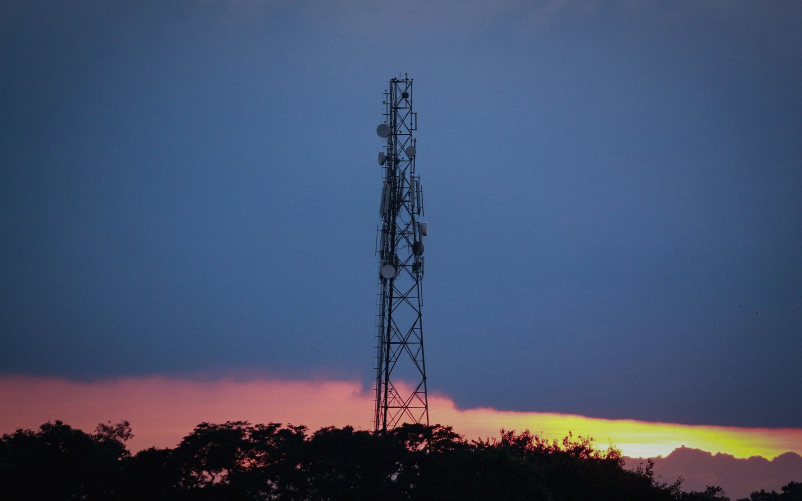
The radiation pattern is simply a map of how the antenna distributes power across all directions. Engineers draw it in two cuts — an azimuth (horizontal) plot showing the compass sweep, and an elevation plot showing the vertical spread. A sector antenna on a mobile base station typically has a horizontal beamwidth of around 60 to 120 degrees, covering a defined wedge of geography. Its elevation pattern has a main lobe aimed slightly downward toward the intended coverage area — called electrical downtilt — and a back lobe suppressed to reduce interference into the cell behind it.
Nulls, the directions where very little power radiates, are not a defect. They are part of the design. The same null that reduces interference in one direction can, however, create a dead spot for a user who wanders into it, which is one reason antenna placement and tilt are careful decisions in network deployment. Modern base-station antennas often allow the downtilt to be adjusted remotely, letting operators tune coverage without sending a climber up the tower.
03Polarisation: the orientation of the wave
When a signal travels through space, its electric field oscillates in a plane. The orientation of that plane is the polarisation. A vertical dipole produces a vertically polarised wave — the field swings up and down. A horizontal dipole produces a horizontally polarised wave. These two orientations are orthogonal to each other, meaning they occupy the same frequency without interfering, and that property is exploited deliberately.
Most modern mobile base-station antennas are dual-polarised, typically with their two elements tilted at plus and minus 45 degrees from vertical. This cross-polarised configuration fits both elements into a single compact housing and conveniently produces two independent signal paths. The receiver can combine them to improve reliability — a technique called polarisation diversity — or a system like MIMO can treat the paths as separate data streams and use both simultaneously.
At the handset end, polarisation matters differently. A phone held in a hand rotates constantly, and its small internal antenna has no fixed orientation relative to the base station. Some polarisation mismatch is unavoidable, which is one reason link budgets include a margin for it. The base-station's cross-polarised feed helps, because whichever orientation the handset happens to present, one of the two cross-polarised elements will have a reasonable alignment.
04The antenna as a system
None of these properties — gain, pattern and polarisation — operate in isolation. An antenna suited to one deployment is wrong for another: the narrow high-gain beam that covers a long corridor is useless on a busy city intersection. What the antenna is actually doing, in every installation, is shaping the electromagnetic field to match the geometry of the coverage problem. The maths behind the shaping is substantial, but the physical intuition — concentrate here, suppress there, match the polarisation — is accessible without any of it.
A horizontal dipole produces a horizontally polarised wave.
From this piece